v8.2 [May 10, 2017]
Schematic editor
Modular design blocks:Reuse existing blocks of circuitry in a snap.
PCB layout editor
New routing engine: Design beautiful PCB layouts fast.
BGA fanout: Escape from your BGA in seconds.
Simplified selection and editing: Select, group, and edit your design, your way.
Online PCB community
One-click make: Generate your CAM outputs with a single click.
One-click MCAD: Fast track your designs to your mechanical tool.
v5.1 [Jul 4, 2008]
XML database structure redesign
Read, edit and parse the data outside of the EAGLE tool
The new XML database structure provides the ability to write scripts that manipulate designs in the EAGLE format which will give users huge productivity benefits. You can make design changes, import information from other designs, and even translate from other formats. This is the first CAD database format to use ASCII text as a format and could become a standard in the industry for communicating designs – making EAGLE the most flexible, user friendly and productive PCB tool on the market.
Design Reuse
Merge board/schematic pairs using the PASTE function with full consistency
You can copy an already finished design consisting of a consistent pair of Schematic and Layout into another project. Enumeration of components and signals will be exactly the same in board and schematic, so that consistency between schematic and board will be maintained. This supports easy design, for example, of multi-channel devices. You only have to design schematic and layout for one channel and can copy it easily.
Routing capability enhancement
Optimize your work-flow with Undo/Redo log
The UNDO/REDO log shows the history of each step you have made. You have full control of the steps going back or forward.
Work with flawless conversions between mm and inches through increased internal resolution (allows grids of 1/4, 1/8, 1/16,1/32 and 1/64 mil)
If you have to work with both systems, metric and imperial, you know about problems that can arise in converting the usual imperial grid values (always divided by 2) and the resulting mm values. Increasing the internal resolution up to 1/64 mil will allow a proper conversion in all situations.
Library editor optimization
Connect a pin to multiple pads
You can now connect one pin in the schematic symbol to any number of pads of the package. With this function EAGLE can handle components internal connected pins. Compared to previous versions schematic symbols look nicer and you save time in defining them.
Draw arbitrary pad shapes easily
Take a pad or an SMD as basis and draw the final contour with the help of the WIRE or POLYGON command. These objects will be considered as part of the pad/smd. No more problems with Design Rules Check for such objects.
Benefit from unlimited number of technologies and package variants
Until now the maximum number of technologies and package variants was limited. In some cases one could reach the limits and had to split a library into two parts. No more limitation in EAGLE 6.
Layout editor add-ons
Dimension your layout automatically
A dimensioning tool where you decide by a few mouse clicks the objects to be dimensioned.
Create restricted areas with Cutout polygons
Outer and inner layers can now have individual restricted areas that will be avoided by signal polygons. Simply draw a polygon and define it as cutout.
File description functionality
Individualize your schematics, sheets, boards and symbols with descriptions
The file description can inform you about the content of a board or schematic. It is shown in the Control Panel without loading the file in the editor windows. This makes your project management clearer. See what this file contains without loading it in an editor window. This also works with sheets of multi-sheet schematics.
ADDITIONAL FEATURES PLANNED FOR VERSION 6:
Routing capability enhancement
Benefit from differential pair routing and automatic meanders
Special signals can be routed with exactly the same length. Differential pair routing is used for pairs of differential (equal and opposite) signals across the board to create a balanced transmission system. Creating meanders helps users automatically give a signal a certain length in the PCB. Meanders in traces are used to increase delay times in high speed digital circuits.
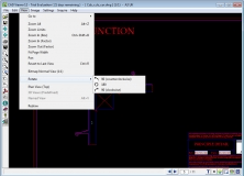
Improve your efficiency through BGA escape routing (ULP)
BGA devices can have a 1000 connections or more. Packages are getting smaller and smaller. It is a hard and tedious work to connect all the pins, set vias, decide about the layers to use, and come out from the BGA area. This ULP helps you in escaping from the BGA in a proper way.
Layout editor add-ons
Be flexible with assembly variants
One schematic but a number of different assembly variants can be handled now.
Justify your text to left, top, right, bottom, middle or center with one mouse click
This allows you to adjust texts as you know it from text editors. Gives a neat look and makes writing, for example, comments more comfortable.
GUI improvement
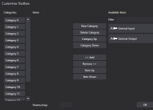
Define your own context menu
Speed up your work-flow with self-defined content in the context menu. Frequently used commands or combinations of commands can be integrated into the context menu. This minimizes mouse-clicks and increases working speed.